2025年6月27日金曜日

RobotStudio® Tutorial – Getting Started 3/5

 RobotStudio® Tutorial – Getting Started 3/5

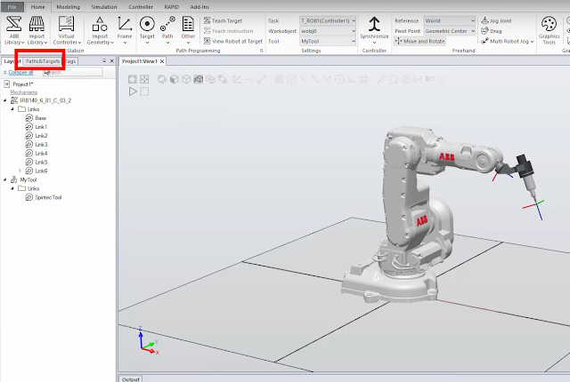
Attaching a tool to a robot flange.


Add Target Points


Right Click and Create Path


🛠️ Procedure: Setting a WorkObject on an Imported Disc in RobotStudio

🎯 Goal:

To create and accurately align a WorkObject to a thin disc geometry (100 mm radius) so the robot can perform operations like sanding relative to the disc’s coordinate frame.


✅ Step 1: Import or Locate the Disc Geometry

  • Ensure your disc is properly imported into the 3D world of RobotStudio.

  • Confirm it's visible in the Layout tab and selectable in the 3D view.


✅ Step 2: Create a New WorkObject

  1. Go to the Home tab → click WorkObjects → choose New WorkObject.

  2. Give it a clear name, e.g., DiscWorkObject.


✅ Step 3: Attach or Align the WorkObject to the Disc

Option A: Use “Attach To” (Recommended if disc appears as selectable object)

  1. Right-click the WorkObject → Modify Position.

  2. In the pop-up, use the “Attach to” dropdown → select your disc from the list.

  3. RobotStudio will auto-align the WorkObject origin to the disc’s local frame (usually its center).

Option B: Manually Measure and Enter Coordinates (For precision)

  1. Use the Measure Tool:

    • Go to the Modeling or Home tab → click Measure Distance.

    • Measure from the world origin or fixture to the center of the disc.

  2. Right-click the WorkObject → Modify Position → enter the measured X, Y, Z coordinates manually.

  3. If needed, adjust the orientation angles (Rx, Ry, Rz) to ensure the Z-axis points normal to the disc surface.


✅ Step 4: Verify and Fine-Tune Orientation

  • Use the axis visual indicators to confirm:

    • Z-axis = sanding tool approach direction (typically perpendicular to disc surface).

    • X/Y-axes = aligned with the disc plane as needed.

  • Use rotation handles or angle input for refinement.


✅ Step 5: (Optional) Attach Disc to WorkObject

  • Drag the disc geometry under the WorkObject in the Layout tree to associate them.

  • This ensures the disc moves with the WorkObject if it's repositioned later.


✅ Step 6: Use the WorkObject in Programming

When defining movement instructions in RAPID, reference the new WorkObject:

MoveL p_SandPoint1, v200, z50, tool0\WObj:=DiscWorkObject;

🔒 Step 7: Lock Position (Optional)

  • Right-click the WorkObject → Lock Position to prevent accidental changes during layout adjustments.


2025年6月16日月曜日

Tool Definition with TCP & Z - ABB RobotStudio

 Tool Definition with TCP & Z - ABB RobotStudio


 https://youtu.be/dKPoA5kXlFM?si=OxnJSW4d7i-nRK7o 


RobotStudio FlexPendant Setup

 RobotStudio FlexPendant Setup


2025年6月15日日曜日

Test Instructions

 Test Instructions


The idea of a modular design for the RAPID code is excellent for achieving flexibility, maintainability, and reusability, especially to accommodate potential part variances in sanding the cantilever base with the ABB IRB 4600-60/2.05 and PushCorp STC1503-BT30 spindle. 

A modular structure with separate modules for the main program, toolpath logic, and target coordinates aligns well with the requirements for flexibility, safety, precision, and optimization. Below, I’ll outline suggestions for structuring the RAPID code and incorporating flexibility to handle part variances, along with considerations for the other requirements (safety, precision, and optimization).

Modular Design Structure
Breaking the RAPID code into modules (e.g., main, toolpath logic, and target coordinates) allows for easier adjustments and maintenance. Here’s a suggested structure:
  1. Main Module:
    • Purpose: Orchestrates the overall program flow, including initialization, safety checks, and calling the toolpath logic.
    • Responsibilities:
      • Initialize robot, spindle, and work object.
      • Perform safety checks (e.g., move to safe home position, verify spindle status).
      • Call the toolpath logic module to execute the sanding operation.
      • Handle error recovery and program termination.
  2. Toolpath Logic Module:
    • Purpose: Defines the logic for generating and executing the sanding toolpath.
    • Responsibilities:
      • Compute the toolpath based on input parameters (speed, feed, force, stepover height/offsets).
      • Incorporate logic to handle part variances (e.g., adjustable offsets or dynamic path adjustments).
      • Ensure collision-free motion using path planning and simulation data from RobotStudio.
      • Optimize cycle time by minimizing unnecessary moves.
  3. Target Coordinates Module:
    • Purpose: Stores and manages target positions and orientations for the toolpath.
    • Responsibilities:
      • Define target points (robtargets) for the cantilever base, either as hardcoded points or dynamically generated based on part geometry.
      • Allow easy modification of coordinates to accommodate part variances (e.g., scaling or offsetting targets).
      • Support work object and tool coordinate system (TCP) definitions for precise tool orientation.
Suggestions for Flexibility to Handle Part Variances
To ensure the RAPID code can accommodate minor part variances (e.g., slight dimensional changes or positioning errors in the cantilever base), consider the following strategies:
  1. Parameterized Variables:
    • Define variables for key parameters like stepover height, offset distances, sanding force, and speed in the toolpath logic module. This allows operators to tweak values without modifying the core logic.
    • Example:
      rapid
      PERS num nStepOver := 2.0; ! Stepover height in mm
      PERS num nOffsetX := 0.0;  ! X-axis offset for part variance in mm
      PERS num nOffsetY := 0.0;  ! Y-axis offset for part variance in mm
      PERS num nSandingForce := 50; ! Sanding force in Newtons
      PERS num nSpeed := 100;    ! Tool speed in mm/s
  2. Dynamic Target Adjustment:
    • Store target coordinates (robtargets) in the target coordinates module and allow for runtime adjustments using offset transformations.
    • Use the Offs function to apply positional offsets to account for part variances.
    • Example:
      rapid
      MODULE TargetCoordinates
          PERS robtarget pBase1 := [[100, 200, 50], [0, 0, 1, 0], [0, 0, 0, 0], [9E9, 9E9, 9E9, 9E9, 9E9, 9E9]];
          PERS robtarget pBase2 := [[100, 220, 50], [0, 0, 1, 0], [0, 0, 0, 0], [9E9, 9E9, 9E9, 9E9, 9E9, 9E9]];
          
          PROC AdjustTargets(num xOffset, num yOffset, num zOffset)
              pBase1 := Offs(pBase1, xOffset, yOffset, zOffset);
              pBase2 := Offs(pBase2, xOffset, yOffset, zOffset);
          ENDPROC
      ENDMODULE
  3. Work Object Calibration:
    • Define a work object (wobjdata) to represent the cantilever base’s coordinate system. Allow the work object’s frame to be adjusted (e.g., via teach pendant or external sensor input) to align with the actual part position.
    • Example:
      rapid
      PERS wobjdata wobjCantilever := [FALSE, TRUE, "", [[0, 0, 0], [1, 0, 0, 0]], [[0, 0, 0], [1, 0, 0, 0]]];
  4. Modular Toolpath Generation:
    • In the toolpath logic module, create procedures that generate the toolpath dynamically based on parameters like stepover height and part dimensions. This allows the toolpath to adapt to slight changes in part size or shape.
    • Example:
      rapid
      MODULE ToolpathLogic
          PROC GenerateToolpath(num stepOver, num width, num length)
              VAR num nSteps := Round(width / stepOver);
              VAR num xPos;
              FOR i FROM 0 TO nSteps DO
                  xPos := i * stepOver;
                  MoveL Offs(pBase1, xPos, 0, 0), vSpeed, zZone, tSandingTool \WObj:=wobjCantilever;
                  MoveL Offs(pBase2, xPos, 0, 0), vSpeed, zZone, tSandingTool \WObj:=wobjCantilever;
              ENDFOR
          ENDPROC
      ENDMODULE
  5. External Input for Variance:
    • Allow the RAPID code to read external inputs (e.g., from a vision system, operator input, or PLC) to adjust offsets or toolpath parameters dynamically. For example, use SocketCom or I/O signals to receive updated offset values.
    • Example:
      rapid
      PROC ReadOffsetFromPLC()
          ! Simulate reading offsets from PLC
          nOffsetX := ReadAnalogInput(1); ! Example: Read X offset from analog input
          nOffsetY := ReadAnalogInput(2); ! Example: Read Y offset from analog input
      ENDPROC
Additional Considerations
To meet the other requirements (safety, precision, optimization), integrate the following into your modular design:
  1. Safety:
    • Safe Home Position: Define a safe home position in the target coordinates module and ensure the robot returns there at the start and end of the program.
      rapid
      MODULE Main
          PERS robtarget pHome := [[0, 0, 500], [0, 0, 1, 0], [0, 0, 0, 0], [9E9, 9E9, 9E9, 9E9, 9E9, 9E9]];
          
          PROC Main()
              MoveJ pHome, v1000, z50, tSandingTool;
              ! Perform safety checks (e.g., spindle status)
              IF CheckSpindleStatus() THEN
                  CallToolpath();
              ELSE
                  TPWrite "Spindle not ready. Aborting.";
                  Stop;
              ENDIF
              MoveJ pHome, v1000, z50, tSandingTool;
          ENDPROC
      ENDMODULE
    • Speed Control: Use VelSet to limit maximum velocity and AccSet to control acceleration for safe operation.
      rapid
      VelSet 100, 500; ! Max velocity 500 mm/s
      AccSet 50, 50;   ! 50% acceleration and deceleration
  2. Precision:
    • TCP Definition: Accurately define the Tool Center Point (TCP) for the PushCorp STC1503-BT30 spindle in RobotStudio and include it in the code.
      rapid
      PERS tooldata tSandingTool := [TRUE, [[0, 0, 100], [1, 0, 0, 0]], [1, [0, 0, 10], [1, 0, 0, 0], 0, 0, 0]];
    • Work Object: Use the work object to ensure precise tool orientation relative to the cantilever base, as shown above.
    • Force Control: If the PushCorp spindle supports force control, integrate the ForceControl instruction to maintain consistent sanding pressure.
      rapid
      ForceControl nSandingForce, [0, 0, 1]; ! Apply force in Z-direction
  3. Optimization:
    • Minimize cycle time by using MoveL for linear sanding paths and MoveJ for rapid repositioning between segments.
    • Reduce unnecessary moves by optimizing the toolpath to follow the cantilever base’s contour efficiently.
    • Use zones (e.g., z10) to blend motions and reduce stopping, improving cycle time without sacrificing precision.
      rapid
      MoveL pBase1, vSpeed, z10, tSandingTool \WObj:=wobjCantilever;
  4. Error Handling:
    • Include error traps in the main module to handle issues like spindle faults or robot collisions.
      rapid
      TRAP SpindleError
          TPWrite "Spindle error detected.";
          MoveJ pHome, v1000, z50, tSandingTool;
          Stop;
      ENDTRAP
Example RAPID Code Outline
Here’s a high-level example combining the modular structure:
rapid
MODULE Main
    PERS robtarget pHome := [[0, 0, 500], [0, 0, 1, 0], [0, 0, 0, 0], [9E9, 9E9, 9E9, 9E9, 9E9, 9E9]];
    PERS num nStepOver := 2.0;
    PERS num nOffsetX := 0.0;
    PERS num nOffsetY := 0.0;
    PERS num nSandingForce := 50;
    PERS num nSpeed := 100;
    
    PROC Main()
        VelSet 100, 500;
        AccSet 50, 50;
        MoveJ pHome, v1000, z50, tSandingTool;
        IF CheckSpindleStatus() THEN
            ReadOffsetFromPLC();
            AdjustTargets(nOffsetX, nOffsetY, 0);
            GenerateToolpath(nStepOver, 100, 200);
        ELSE
            TPWrite "Spindle not ready. Aborting.";
            Stop;
        ENDIF
        MoveJ pHome, v1000, z50, tSandingTool;
    ENDPROC
ENDMODULE

MODULE ToolpathLogic
    PROC GenerateToolpath(num stepOver, num width, num length)
        VAR num nSteps := Round(width / stepOver);
        VAR num xPos;
        FOR i FROM 0 TO nSteps DO
            xPos := i * stepOver;
            MoveL Offs(pBase1, xPos, 0, 0), vSpeed, z10, tSandingTool \WObj:=wobjCantilever;
            MoveL Offs(pBase2, xPos, 0, 0), vSpeed, z10, tSandingTool \WObj:=wobjCantilever;
        ENDFOR
    ENDPROC
ENDMODULE

MODULE TargetCoordinates
    PERS robtarget pBase1 := [[100, 200, 50], [0, 0, 1, 0], [0, 0, 0, 0], [9E9, 9E9, 9E9, 9E9, 9E9, 9E9]];
    PERS robtarget pBase2 := [[100, 220, 50], [0, 0, 1, 0], [0, 0, 0, 0], [9E9, 9E9, 9E9, 9E9, 9E9, 9E9]];
    
    PROC AdjustTargets(num xOffset, num yOffset, num zOffset)
        pBase1 := Offs(pBase1, xOffset, yOffset, zOffset);
        pBase2 := Offs(pBase2, xOffset, yOffset, zOffset);
    ENDPROC
ENDMODULE
Final Notes
  • Test in RobotStudio: Use RobotStudio to simulate the toolpath with the SAT file assembly to ensure collision-free operation and validate the sanding process for both parts of the cantilever base.
  • Document Adjustments: Include comments in the RAPID code to explain how operators can modify variables like nStepOver or nOffsetX to handle part variances.
  • Spindle Integration: Verify the PushCorp STC1503-BT30 spindle’s force control and speed settings are correctly integrated into the RAPID code, as these are critical for sanding quality.